
This cell has been
intentionally left blank.
This cell has been
intentionally left blank.
This cell has been
intentionally left blank.
|
|
|
|
|
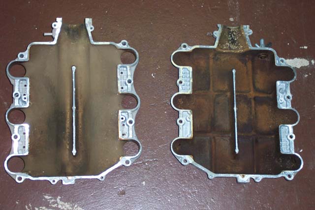
| Top and Bottom Portions of the original
plenum |
Bottom half of plenum, divider removed |
Top half of plenum, divider removed |
Bottom half of plenum, another look |
|
|
|
|
|
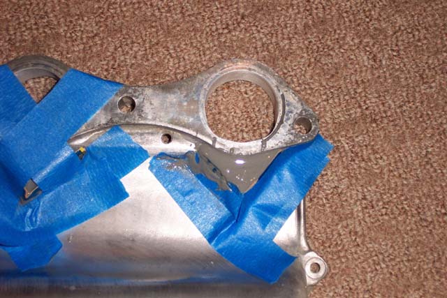
| JB Weld used to build up the bottom of
the bottom half of the plenum. Cardboard pieces are taped in place
to shape the JB Weld. |
After the JB Weld dried |
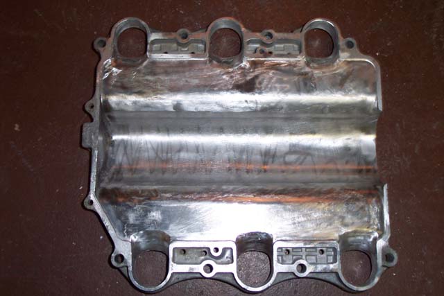
Major port of bottom half of plenum. Notice
the JB Weld peaking through. |
220 grit sandpaper taped to a 3/4" sanding
drum and used for final sanding |
|
|
|
|
|
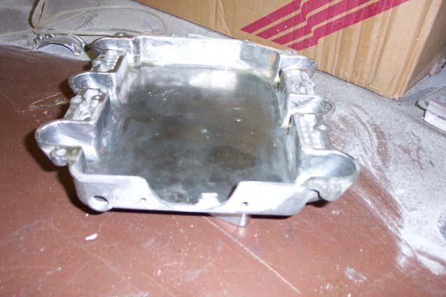
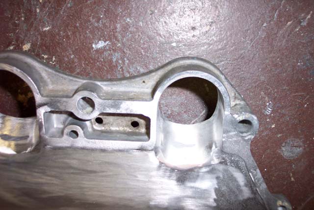
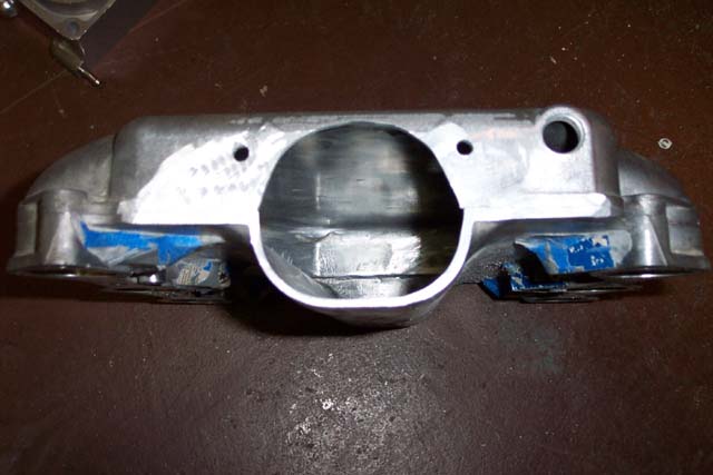
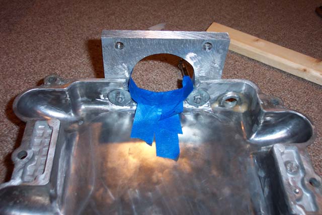
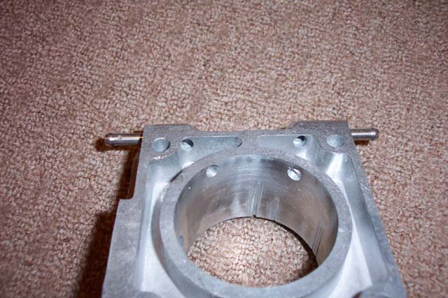
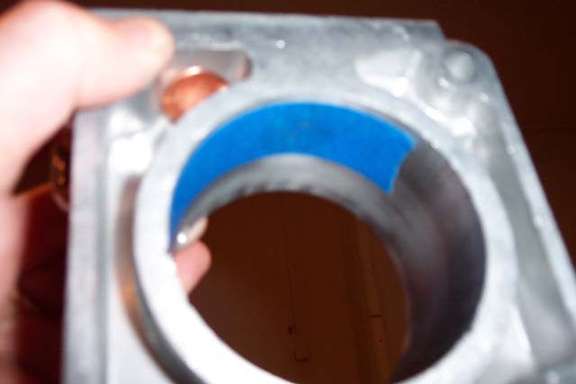
| Plenum end view without neck. The
height of the opening is almost exactly 70mm. |
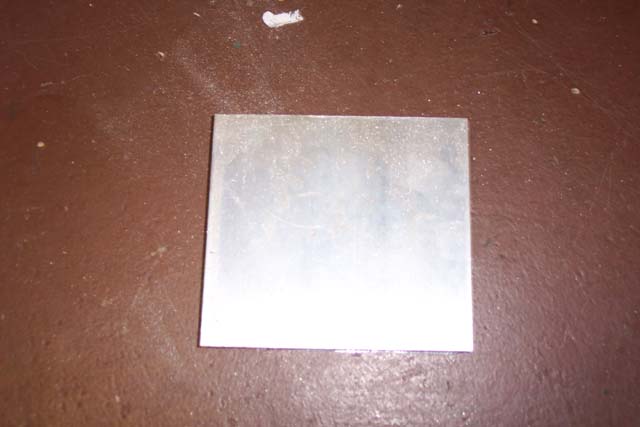
4"x5"x1/2" piece of aluminum from www.onlinemetals.com. |
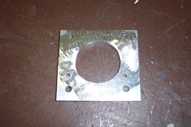
Home made spacer created using a drill,
a jigsaw, and some sanding drums. The surface was roughed
up with the angle grinder. |
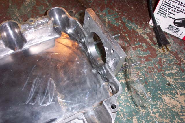
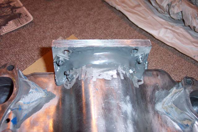
Plate is bolted to the top of the plenum
using two small machine screws. Prior to bolting, JB Weld is applied
to the surface between the two pieces and to the bolts. |
|
|
|
|
|
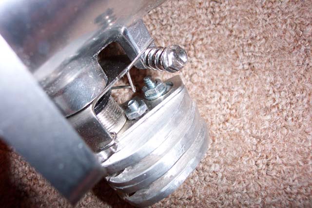
| Tape is used so that the JB Weld will drip
in and form a smooth surface when applied. Also note that the
spacing of the small bolt heads used to join the plate and the plenum
fit into the groove of the EGR plate perfectly. |
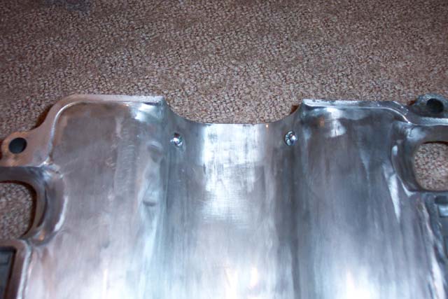
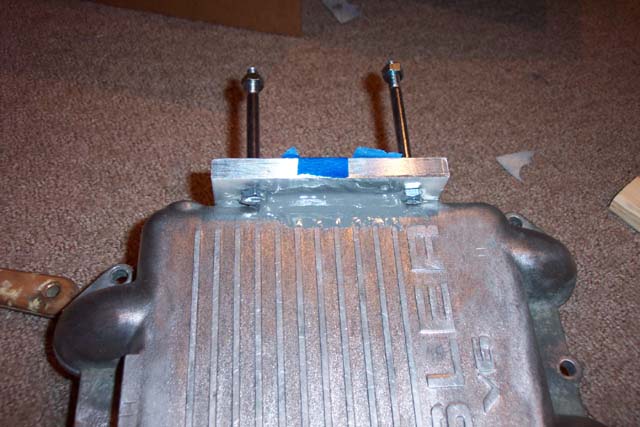
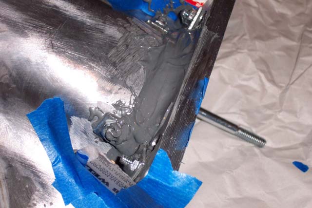
Top view of plenum attached to spacer.
Two long bolts were inserted at this time. The heads are
ground down slightly to fit in the curve between the plenum and the plate.
JB weld fills the valley between the two. |
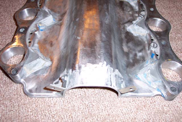
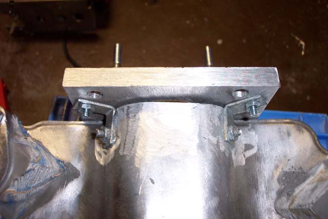
90 degree steel brackets are held to the
lower plenum with machine screws. JB Weld is used around the screws
for additional support and to seal the holes. |
Lower half of plenum with the plate up
against it. |
|
|
|
|
|
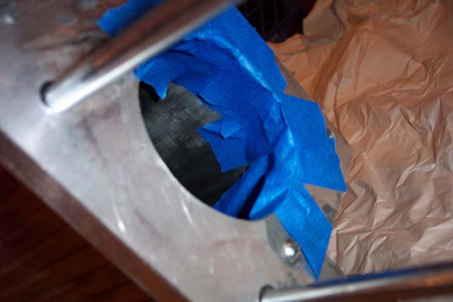
| Tape the top half to once again, make a
good surface with JB Weld. |
Bottom half of plenum is held to the plate
with machine screws and JB Weld is applied. Note, the heads of
these screws do not fit in the grooves of the EGR spacer and required
countersinking in the aluminum plate. |
Another view. Note the way tape was
used to shape the JB Weld. |
70mm Mustang EGR spacer with two small
holes drilled to get vacuum to the vacuum ports. Apparently on
the Mustang, the seal isn't made on the inner ring. |
|
|
|
|
|
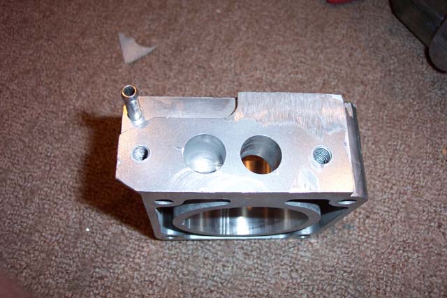
| Side view of EGR spacer. A piece
of metal has been ground off of the side of the original plate (not
shown in any pictures). |
Penny used to block one hole. Masking
tape used to block the other |
Both holes filled with JB Weld |
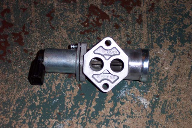
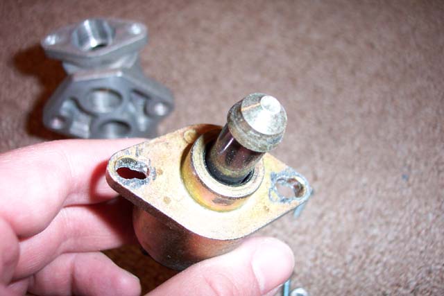
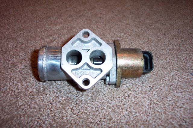
This is an `86-92 Mustang AIC. It
is like an AIS however rather than a pintle that moves in and out, a solenoid
moves a stick with a ball on it back and forth |
|
|
|
|
|
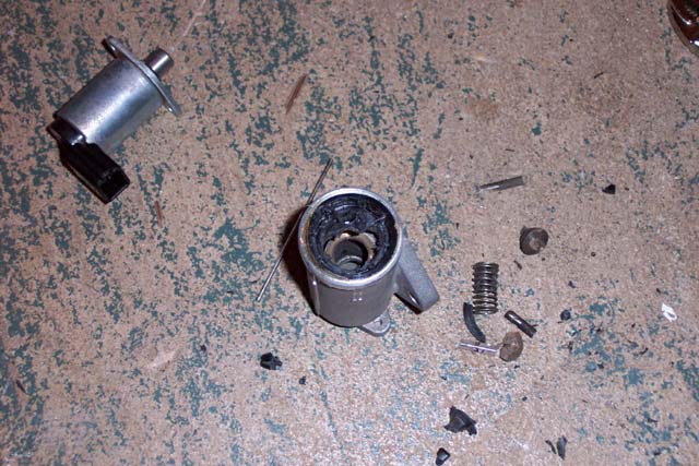
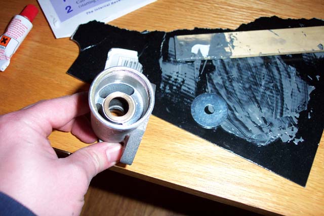
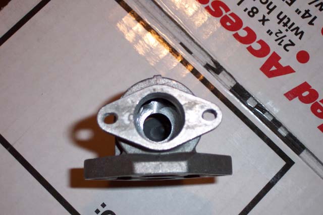
| Gut the AIC. ($10 on eBay) |
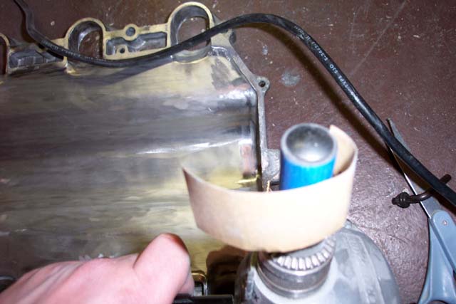
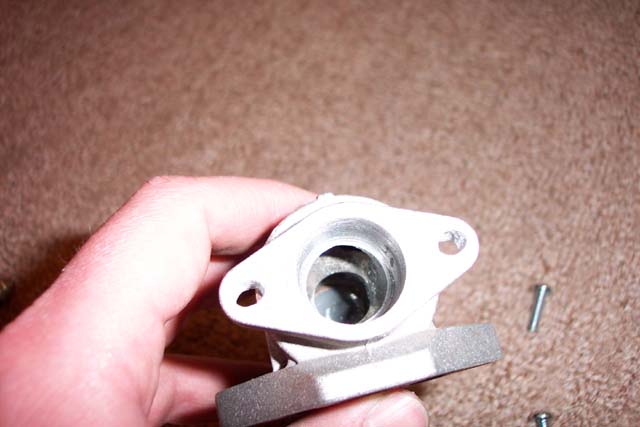
Bore the top of the AIC housing out a little
bigger so that the base of AIS will fit in it |
Plug up the end with JB Weld and a large
fender washer. |
End plugged with JB Weld |
|
|
|
|
|
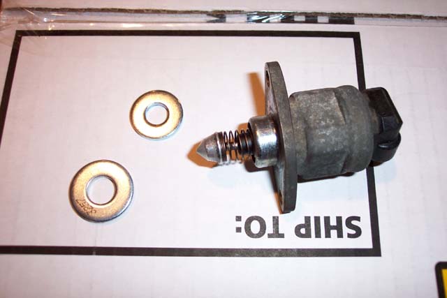
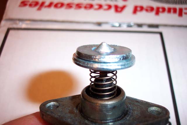
| A view of the AIS. An AIS from a
Jeep was used initially but in later stages of the project, the stock
AIS from my Daytona was used. The only difference is the color and
the shape of the pintle. Note the way the bolt holes have been widened. |
A view of the stock AIS (which was used
rather than the Jeep AIS because of the shape of the pintle). Note
the 5/16" and 3/8" washers. |
The washers fit the stock pintle perfectly.
The 3/8" washer rides right up against the lip of the pintle. The
5/16" one fits perfectly on top of the first. These washers will be
used to make a hole that the AIS can block or unblock to control the idle. |
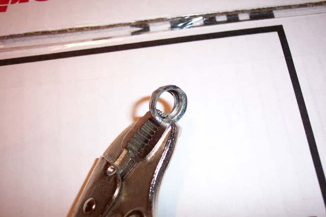
The washers were placed on the end of the
AIS, clamped together with a pair of vise grips, and then ground down with
an angle grinder. After grinding, superglue was used to hold the washers
together before they were epoxied into the AIC housing. |
|
|
|
|
|
| There is a curved (taco shaped) surface in the
middle of the AIC housing. Grind it flat so that reducing washers
can be inserted to narrow the opening. JB Weld was used to glue the
washers into place, and it was a real pain to get the washers to sit level
(not shown). |
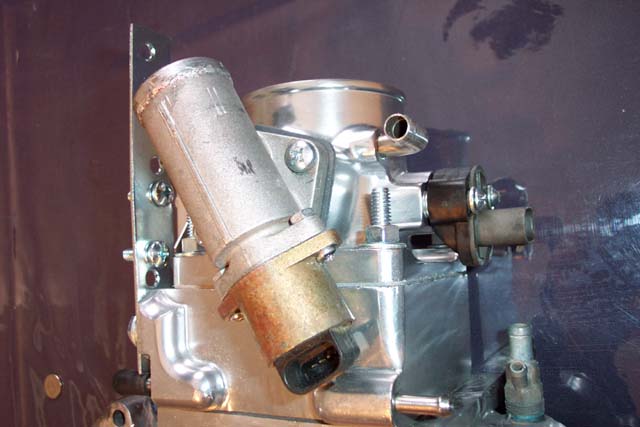
AIS bolted onto AIC housing. In order to
do this, the holes both the AIC housing and the AIS were drilled bigger.
This picture was taken before the reducing washers were added to the
AIC housing. Otherwise, they would be just barely visable in the
right hand opening. |
AIC installed using cross threaded 1/4 machine
screws. |
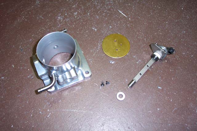
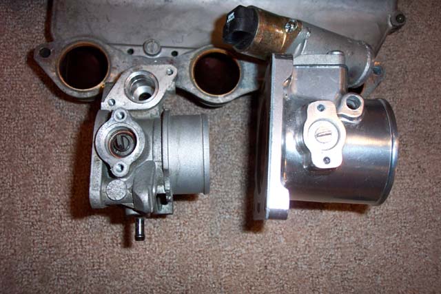
`86-92 70mm Mustang throttle body disassembled
(MAC version) ($150-$170 w/ EGR spacer on eBay) |
|
|
|
|
|
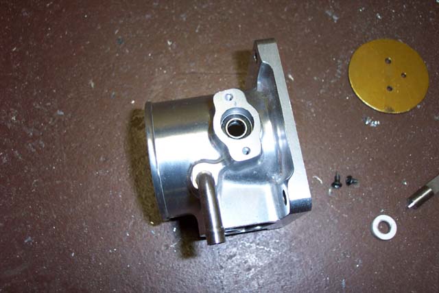
| Bore the opening for the TPS sensor slightly
to accept the Chrysler TPS. Also, shave 1/16" off of each side
of the end of butterfly shaft so that it will fit inside the Chrysler
TPS (not shown). |
Bolt 2 1/2" pieces of aluminum together
and us a jigsaw, angle grinder, and dremel to make a cable holder like
the one on the Chrysler throttle bodies. This just bolts to the flat
panel on the Mustang TB. |
Another view of cable holder. The
dips that the cables sit in were created using an angle grinder while
holding the aluminum with a C-clamp. |
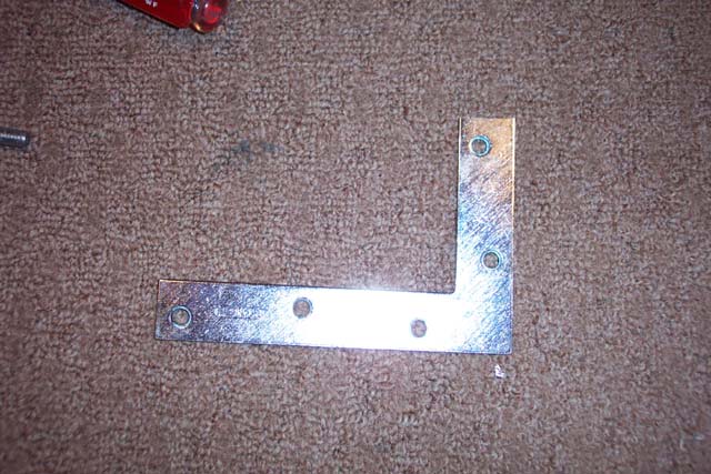
This is a 4"x4" corner support from Home
Depot (~$1) Once side is cut to the height of the TB. The
other side will be bolted to the bracket that holds the cable sleves.
Additional holes were drilled that are not shown in the picture. |
|
|
|
|
|
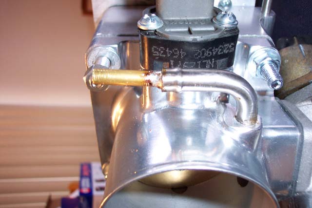
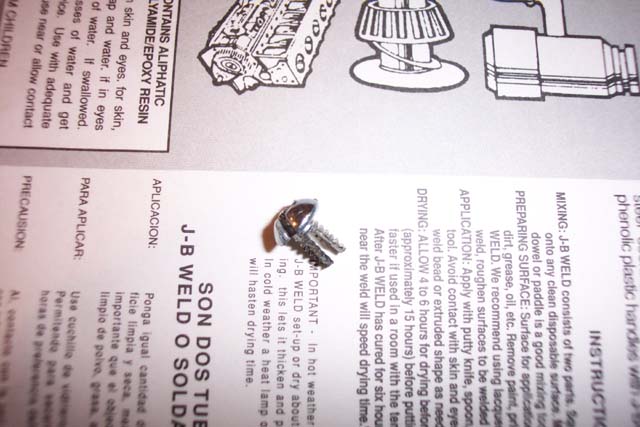
| 1/4" piece of copper tubing soldered into the
Mustang vacuum port (~$1 at Home Depot). Vacuum port has also
been twisted upward using a pair of pliers. It is just rotated
but still very firmly attached. |
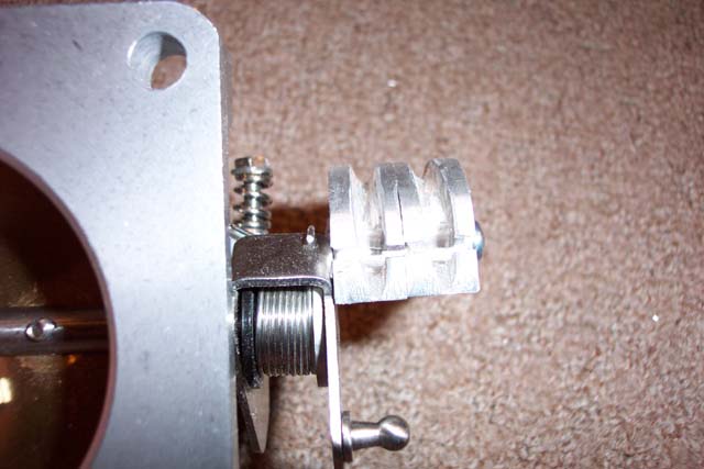
The TPS is held on with machine screws that
are cross threaded. It is also supported but some small washers
between it and the throttle body. Not using the washers puts pressure
on teflon ring around the shaft and prevents the valve from closing. |
Note the difference in angle between the blade
on Chrysler and Ford throttle bodies. Failure to address this will
result in a code "24" from the computer. |
In order to get around the angle difference,
I used a dremel to notch the head of a machine screw so that it can fit
inside the TPS. I then cut a slot in the shaft of the screw to fit
around the blade of the TB. This involves some trial and error but
I got it to fit on the second try. |
| ,
|
|
|
|
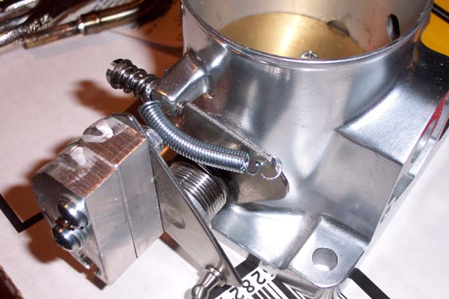
| The Ford spring is VERY weak compared to the
typical Chrysler spring. To make the pedal a little firmer, I added
a supplemental spring. |
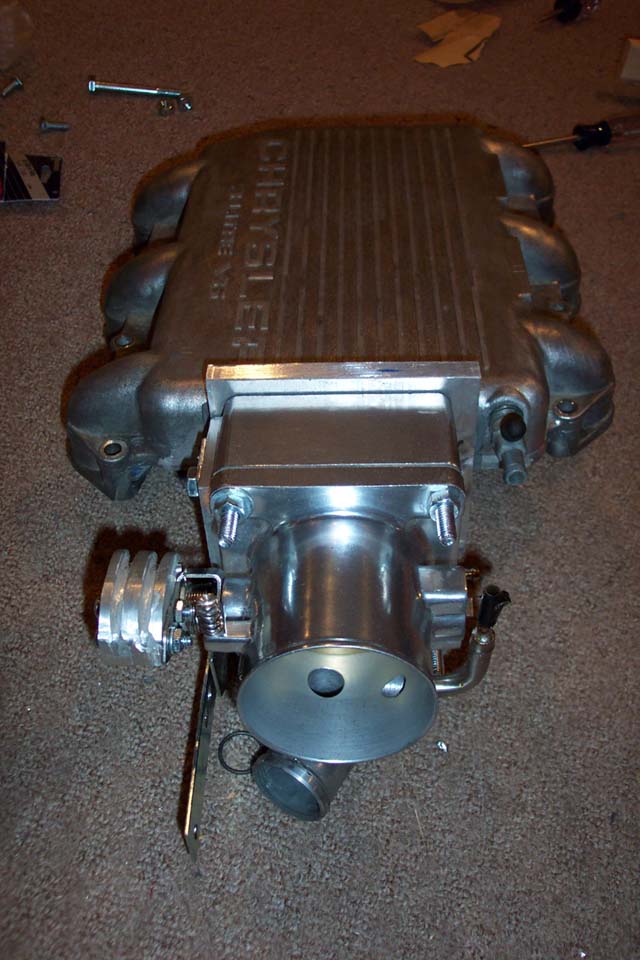
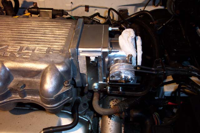
The beast assembled minus the TPS. This
is huge, but the hood shuts and it doesn't hit anything else under the
hood. |
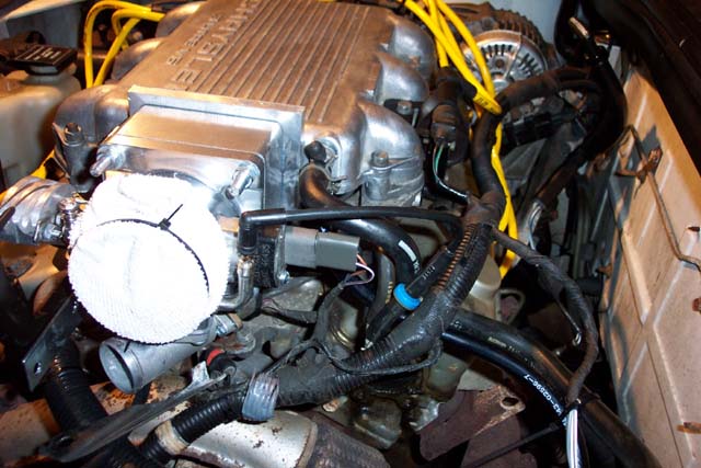
Picture of the TB installed on the car |
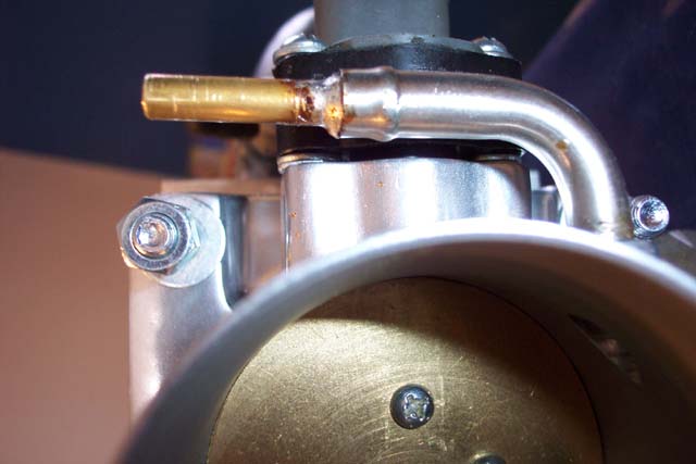
End view of TB installed on the car. Note
that the vacuum tubes connect but require some bending. |
|
|
This cell has been intentionally left blank. |
This cell has been intentionally left blank. |
This cell has been intentionally left blank. |
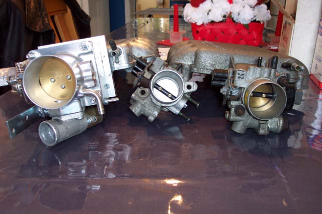
| TB comparison. 70mm Mustang on
the left. 46mm in the middle. 52mm on the right. |